M-53 (Van Dyke Ave) Rehabilitation
Spalding DeDecker (SD) was retained by the Michigan Department of Transportation (MDOT) to provide complete design for the rehabilitation of a 2.85-mile-long section of M-53 (Van Dyke Ave) from Helen St to the Red Run Drain in the cities of Warren and Center Line in Macomb County. This section of M-53 (Van Dyke Ave) is predominantly 7 lanes wide.
Road and Street Design / Roadway Rehabilitation & Rural Freeways
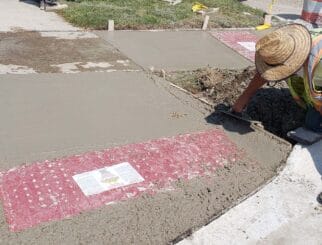
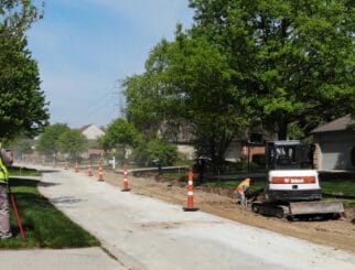
The project scope called for a comprehensive rehabilitation that included extensive pavement repairs, cold-milling HMA pavement, minor geometric improvements, replacement of all curb & gutter and driveway approaches, crown correction, HMA overlay, upgrading of approximately 130 ADA sidewalk ramps, signal replacements, guardrail replacement, and non-freeway sign upgrading for 2014 construction. All design was done in accordance with MDOT 3R and AASHTO standards, specifications, and procedures. The project included a safety analysis of all accidents and intersections, maintaining traffic plan, permanent pavement marking plan, and non-freeway signing plan, as well as design and construction drawings and specifications. The project involved context sensitive design to minimize disturbing the well-developed commercial corridor. ROW plans were developed after real estate needs were determined in order to provide enough room for proposed ADA sidewalk ramp improvements and/or signal replacements. A design exception for lane widths was required, because the 11-foot-wide existing lanes from Helen St to 12 Mile Rd for a trunkline on the National Truck Network (NTN) could not be widened to 12 feet in order avoid impacting roadside features in this densely developed urban location. Minor drainage improvements within the project limits included cleaning drainage structures and sewer leads, and investigating localized drainage issues at the southbound right-turn lane from M-53 (Van Dyke Ave) to Tank Ave. Geometrics of existing turn lanes and intersection radii were evaluated and improved where possible. Also, the existing “jug handle” configuration in the northeast quadrant of the Chicago Rd intersection was evaluated to see if it could be eliminated in favor of direct left-turns to Chicago Rd. However, traffic modeling showed that intersection left-turn movements operated at a better level-of-service if the existing “jug handle” was left as is. Engineering cost estimates were developed in SAPW (Stand-Alone PES Worksheet). A CPM (Critical Path Method) construction schedule was also developed using Microsoft Project.
Safety Studies
SD performed a safety review and crash analysis for accidents that occurred over the previous five years. The crash analysis included the analysis of all signalized intersections as spot locations and the roadway segments between the signalized intersections. Intersections that exceeded thresholds for number of crashes were analyzed for specific crash types. Countermeasures were recommended where needed. SD then conducted a field investigation at those locations to identify potential mitigation options. In addition, SD submitted Design Exception Requests and conducted site-specific crash analyses for each of those sites, as well as time-of-return analyses for all recommended countermeasures. SD also evaluated an access management study which recommended closing or consolidating several driveways, and determined which driveways could feasibly be consolidated or eliminated with the project to improve safety along the M-53 corridor.
Pavement Markings
Pavement marking plans were developed as a part of this project. The pavement marking plans reflected current MDOT standards and specified material, color, and type. The pavement markings varied from short sections of divided roadway section to a multi-lane roadway and the various transitions required to sufficiently delineate traffic lanes.
Road & Bridge Design Surveys
SD performed a topographical survey for the road project. Mapping included obtaining pavement cross-sections in several areas, locating surface features, underground utilities and surface drainage, and creating a Digital Terrain Model (DTM). Data was compiled in Power GEOPAK V8i SS2 using MDOT’s workspace settings for Power GEOPAK and submitted in a separate survey portfolio to MDOT.


